Waiting for a break in the workload to write this post has proven futile. So at the risk of delaying project delivery an hour or 3, I thought I’d get this one published before all continuity is lost. Rules of thumb for welds and bolts are OK, but what about more substantial structural members?
Many machines include components that support loads by bending resistance. We’d normally call them beams. Engineers routinely calculate bending stresses using ‘M on Z’, an equation stemming back to work by Euler and Bernoulli in the 1700’s. Calculation of the bending moment (M) requires knowledge about the applied load (see the November 13, 2014 post “Mass Destruction” for some tricks to help with this). Depending on the beam cross-section, section modulus (Z) calculations might demand a few pages of mathematical gymnastics. Of course spreadsheets and similar tools ease the burden somewhat, and dedicated structural analysis packages, or even smartphone apps, can remove mental effort almost entirely. Additionally, safe load or design capacity tables are available for many standard structural sections (for example, the Australian Institute of Steel Construction publishes a range of such tables). But what if no such aids are handy and/or you need a quick reality check for the I-section about to be used as a lifting beam?
Cutting to the chase:
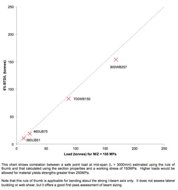
The safe mid-span load (in tonnes) on a simply supported beam = 6% of BTD ÷ L
“B” is for breadth, or the width of each flange. “T” is the thickness of each flange. “D” is the section depth, i.e., the distance between the 2 flanges. And “L” is the span between supports.
Running your tape over the beam sitting at the lifting site, you find B ~ 135mm, T ~ 10mm, D ~ 210mm, and L ~ 3500mm. A minute later you’re asking to see the lifting beam validation for the planned 10 tonne lift – your quick check suggests the beam is barely adequate for half the known load (135 x 10 x 210 ÷3500 x 6 ÷100 ~ 4.9 tonnes). Disaster averted!
If the load is uniformly distributed instead of a point load at mid-span, then the safe load estimated using the rule of thumb above can be doubled. Only one quarter of the calculated load is allowed if the beam is cantilevered from one end rather than supported at each end. For example, a 4m cantilever using a 310UB46 (B = 166mm, T = 11.8mm, D = 307mm) would have an estimated safe uniformly distributed load of 166 x 11.8 x 307 ÷ 4000 x 6% x 2 (for uniform loading) ÷ 4 (for a cantilever) = 4.5 tonnes. Alternatively, the same cantilever could sustain about 2.25 tonnes if point loaded at the free end.
As with all rules of thumb, the caveats are important. This rule is based on a safe working stress of 150MPa, which would be appropriate (in Australia) when using 250MPa yield strength material. However, it considers bending about the strong I-beam axis only; it does not consider axial loading, superimposed bending about the weak axis, web shear stresses, or lateral torsional buckling. It offers a quick reality check of existing beams or first-pass design sizes, but more detailed analysis cannot be omitted.
You could also use the welding rule of thumb (“Making Welds Stick”, October 5, 2014) to check the welds at the beam lifting lugs, and the bolting rule of thumb (“Nailing it with Bolts, July 31, 2014) for a quick check of the D shackle shear capacity. These are very handy tricks, but remember they must not replace the formal design calculations they are intended to check.
That’s enough for now on simple design rules of thumb. My current plan is to add a few quick entries about longwall hydraulic system characteristics, but please do not hesitate to make other suggestions or to ask questions. Please feel free to subscribe and receive notifications when new posts are published.


